
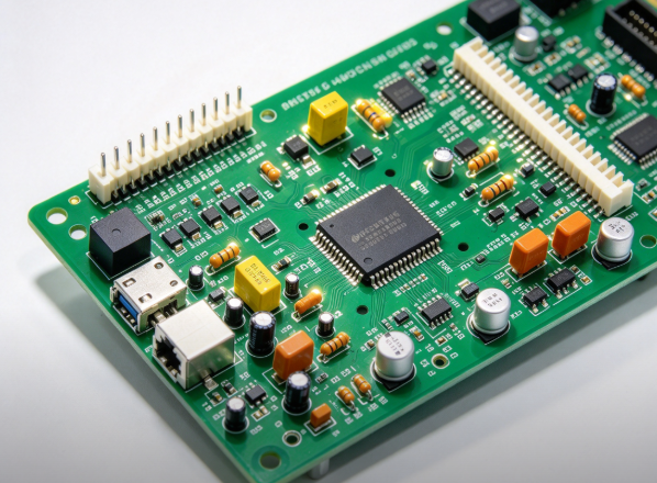
DIP Assembly Service
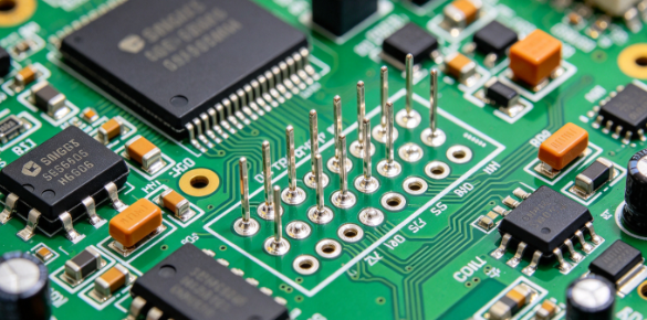
DIP assembly (Dual In-line Package assembly, also known as THT or through-hole technology assembly) refers to the process of inserting leaded through-hole components (such as DIP resistors, capacitors, ICs, and relays) into drilled holes on a PCB and then soldering the leads in place using wave soldering (or manual soldering).
Our DIP through-hole assembly delivers robust mechanical bonding, ideal for high-vibration, high-current and heavy-component applications. We support pure DIP assembly as well as combined SMT + DIP hybrid PCBA manufacturing for prototypes and bulk orders.
Key Points:
- Drilling required: DIP component leads must pass through pre-drilled through-holes in the PCB.
- Soldering method: Wave soldering is the standard (solder waves wash over the underside of the board to solder the leads), while manual soldering is used for small batches or prototyping.
- Lead configuration: Dual In-line Package (DIP-8, DIP-40, etc.) with leads arranged along two sides.
- Relationship with SMT: DIP is a classic example of THT (Through-Hole Technology), contrasting with SMT (Surface Mount Technology).
- Characteristics: High mechanical strength, straightforward soldering, and easy rework; however, it occupies significant space, offers low component density, and does not support double-sided mounting.
Applications: High-current components (connectors, power modules, relays), areas requiring high mechanical strength, and some legacy ICs; in modern products, DIP is retained only where SMT cannot meet requirements (e.g., high current or mechanical stress).
DIP Assembly Specifications
✅ Component Range: Through-hole resistors, capacitors, DIP ICs, relays, terminal blocks, power connectors, electrolytic capacitors
✅ Pin Pitch: 2.54mm standard DIP pitch, custom through-hole pins available
✅ PCB Thickness: 0.8mm – 4.0mm
✅ PCB Size: Min 10mm × 10mm, Max 1200mm × 600mm
✅Assembly Side: Single-sided DIP, Double-sided DIP, Hybrid SMT+DIP
✅Volume Support: Prototyping, Small batch & Mass wave soldering production
✅ Post Assembly Test: Visual Inspection, Continuity test, Functional Test(FCT)
✅ File Required: Gerber files, BOM list, Component placement drawing
Our DIP Production Workflow
- 1. Gerber & BOM Review: Our engineering team checks your PCB design and BOM, confirms through-hole component availability and provides DFM suggestions.
- 2. Component Preparation: Components are sorted and prepared according to BOM list before insertion.
- 3. Component Insertion: Operators insert through-hole component leads into PCB drilled holes.
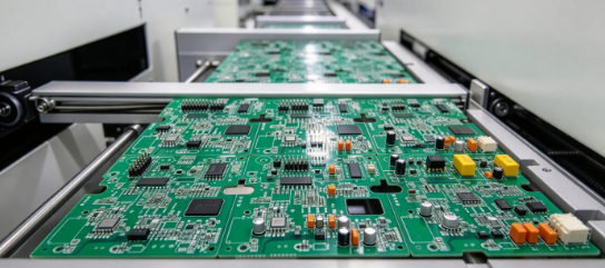
- 4. Wave Soldering / Selective Soldering: PCBs go through wave soldering machine to solder all through-hole pins steadily. Manual soldering for special samples.
- 5. Visual Inspection: QC inspects solder joints for cold solder, bridging, missing parts and polarity errors.
- 6. Functional Testing (FCT): Custom electrical test available to validate board performance as your requirement.
- 7. Packing & Delivery: Anti-static packaging for safe shipment worldwide.
Our DIP Assembly Advantages
Superior Vibration & Shock Resistance
Pins penetrate through PCB substrates and are soldered on the opposite side, forming robust solder joints. It works reliably under vibration and mechanical impact for devices deployed in harsh industrial environments.
Convenient Rework & Maintenance
Through-hole components can be readily desoldered and replaced, simplifying circuit debugging, prototype modification and on-site repair work.
High-Current Power Component Compatibility
THT assembly suits large connectors, high-current capacitors and power modules, ideal for heavy-load power applications beyond the capacity of SMD devices.
Legacy Through-Hole Component Support
Many traditional electronic parts are only available in through-hole packages, which can only be assembled via THT soldering processes.
Simplified Manual Visual Inspection
Exposed pins and solder joints on both sides of the PCB streamline manual quality checks, allowing fast identification of assembly defects.
Frequently Asked Questions
Q: What is the MOQ for DIP assembly service?
A: We have no strict MOQ requirement. We accept prototype, small batch and mass production DIP assembly orders to match your project needs.
Q: What soldering methods do you use for DIP assembly?
A: Wave soldering is applied for mass production of through-hole boards. Selective soldering is used for hybrid SMT+DIP PCBA. Manual soldering is available for prototypes and low-volume orders.
Q: What industries typically use DIP / THT PCBA?
A: DIP THT PCBA is widely used in industrial control, power supply, automotive electronics, security equipment and heavy-duty devices requiring high mechanical reliability.
Q: What is your lead time for DIP PCBA?
A: DIP prototype order normally takes 4–7 working days. Mass production lead time depends on PCB quantity, component sourcing status and board complexity.
Q: What inspection steps do you use for DIP boards?
A: Visual inspection for all DIP solder joints. We check cold solder, bridging, missing parts and polarity errors. Extra electrical testing is available upon request.