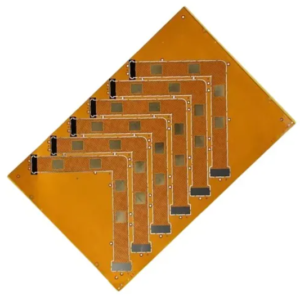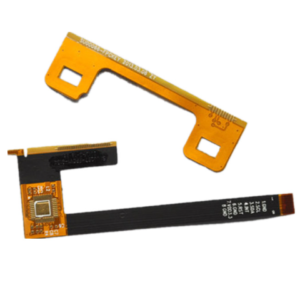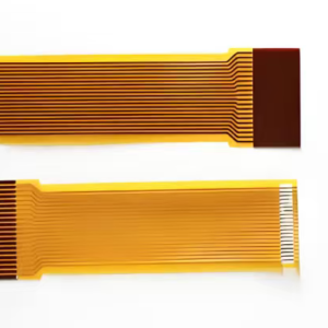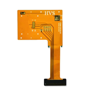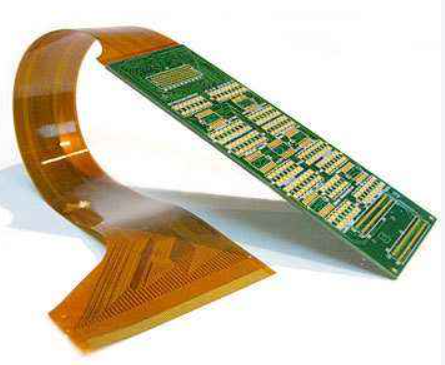
Long Bendable Zone Extended Polyimide Flex PCB Board is a custom rigid-flex circuit with an extra-long continuous polyimide flexible segment, designed for large-radius looping and reciprocating motion inside scanners and optical equipment.
Key Benefits
✅ Extra-long continuous polyimide flex zone, support large-radius looping & circulating routing for internal space layout
✅ Integrated rigid and flex structure, no intermediate connectors, reduce signal loss and contact failure
✅ Rolled annealed RA copper for extended flex area, excellent fatigue resistance for repeated large-loop bending
✅ Adhesiveless PI coverlay optional for low ionic contamination, stable performance for optical & precision imaging equipment
✅ Custom flex length, bend radius, stack-up and trace impedance to match scanner, camera and display module requirements
✅ Low outgassing PI material option available, suitable for sealed optical cavity environment
✅ Eliminate cable harness assembly, simplify mechanical structure and cut BOM & assembly cost
✅ Prototype and low-to-medium volume fast turnaround service for optical R&D verification
Specifications
| Item | Specification |
|---|---|
| Product Name | Long Bendable Zone, Extended Polyimide Flex PCB Board |
| Rigid Material | FR4 / High Tg FR4 |
| Flexible Core Material | Polyimide (PI) film |
| Coverlay | Adhesive PI coverlay / Adhesiveless PI coverlay (recommended for long flex zone) |
| Layer Count | 2~8 layers |
| Copper Foil | RA Rolled Annealed Copper (Flex zone priority), Electrolytic copper (rigid area) |
| Copper Thickness | 0.33oz, 0.5oz, 1oz |
| Min Line / Space | 0.08mm / 0.08mm |
| Extended Flex Length | Custom, can support ultra-long continuous flex section upon request |
| Recommended Bend Radius | ≥ 8 × flex core thickness (long loop design rule to avoid trace crack) |
| Surface Finish | ENIG, Hard Gold, OSP, Immersion Silver |
| Operating Temperature | -40℃ ~ 125℃ |
| Flex Cycle Life | ≥50,000 cycles (RA copper + adhesiveless coverlay, large radius bending) |
| Tolerance | Outline ±0.10mm; trace width ±0.03mm |
| Special Option | Low-outgassing PI, low-ion coverlay for optical sealed module |
Design Principle
This rigid-flex PCB adopts an integrated lamination structure with an extra-long continuous polyimide flexible segment connected to rigid FR4 functional area.
- The long PI flex zone is specially designed for large circular looping, winding and routing inside narrow, curved mechanical cavities (scanner travel channel, optical sliding assembly).
- All signal traces run continuously from rigid component area through the extended flex tail, without split joints or FPC connectors, keeping transmission path integrated.
- Stack-up adopts symmetrical construction to reduce board warpage after lamination and temperature cycling.
- Sensitive high-speed traces are arranged away from sharp stress points; all openings on coverlay use rounded edges to release bending stress.
- No SMT components or vias are placed within the long dynamic bendable zone, avoiding solder joint fracture under cyclic looping movement.
Solder Mask & Coverlay Characteristics
- Rigid Area: Liquid photoimageable solder mask Green / black matte or glossy solder mask; insulation, anti-bridging during soldering, resist cleaning solvent.
- Extended Long Flex Zone: PI Coverlay (no liquid solder mask)
- Adhesiveless coverlay preferred for this long-bend design: less residual adhesive, lower ion migration, better flexibility and less aging after repeated looping.
- Adhesive-type coverlay for cost-sensitive projects; not recommended for frequent cyclic bending.
- Coverlay windows use rounded corners; silkscreen printing on long flex section is minimized, printing ink will become brittle and crack under continuous bending.
Manufacturing Advantages
- Special long-flex lamination process, control residual stress inside the extended PI tail to prevent natural curling.
- Laser cutting for coverlay and flex profile: clean, burr-free edges, reduce stress concentration points.
- Plasma desmear process for interlayer vias, reliable interconnection.
- 100% electrical open/short test; bending fatigue sample validation available for optical equipment projects.
- Strict dimensional control on long flex length, guarantee fit for scanner sliding track assembly.
- IPC-6013 rigid-flex compliance, material certification provided for optical and medical imaging customers.
Application Scenarios
- Flatbed & document scanner internal moving scanning head flex connection
- Optical inspection equipment, machine vision sliding camera module
- Medical endoscope imaging transmission link
- Portable imaging detector
- Display moving tail connection, curved internal routing equipment
- Precision sliding and reciprocating motion electronic assemblies