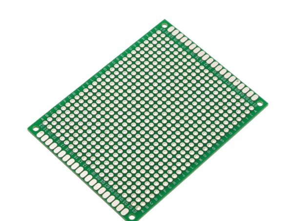
I. Specifications
| Item | Specification |
|---|---|
| Product Name | 2.54mm Pitch FR4 Breadboard PCB / Prototyping PCB |
| Base Material | FR-4, TG130 / TG150 optional |
| Board Thickness | 1.6mm (standard), 1.2mm optional |
| Pitch | 2.54mm (0.1 inch) standard header pitch |
| Copper Foil | 35μm (1oz) / 70μm (2oz) |
| Surface Finish | HASL, OSP, ENIG optional |
| Solder Mask | Green solder mask (default), black/blue available |
| Silkscreen | White legend, clear grid marking |
| Grid Layout | Standard matrix grid, horizontal & vertical 2.54mm spacing |
| Hole Size | 1.0mm finished hole, fit 0.8mm pin / 2.54mm pin header |
| Min Track / Space | 0.2mm / 0.2mm |
| Operating Temperature | -40℃ ~ +105℃ |
| Dielectric Constant Dk | ~4.2 @ 1GHz |
| Insulation Resistance | ≥ 10¹² Ω |
| Voltage Rating | DC up to 300V |
| Layer Count | 1 layer / 2 layers (most common for breadboard pcb) |
| Tolerance | Hole & outline tolerance ±0.1mm |
| Compliance | RoHS, REACH |
II. Features
- Standard 2.54mm (0.1″) grid pitch, fully compatible with 2.54mm pin headers, dupont wires, IC sockets and through-hole components.
- FR4 substrate provides good mechanical strength and flatness, not easy to warp during hand soldering.
- Flexible prototyping layout: users can solder jumpers, resistors, capacitors, ICs and modules freely on the grid.
- Clear silkscreen grid lines help quick component placement and wiring arrangement.
- Wide working temperature range, suitable for lab test, student training, hobby DIY and pre-production prototype verification.
- Low cost, fast lead time for small batch prototype orders.
- Single-sided version for simple circuit; double-sided version allows bottom-layer jumper wiring for complex prototypes.
III. Design Principle
This breadboard PCB follows the universal 0.1-inch grid standard for through-hole electronics:
- 2.54mm grid system: The whole board is arranged by fixed 2.54mm hole matrix. This is the industry standard spacing for through-hole DIP ICs, pin headers and sockets.
- Hole design: 1.0mm finished holes are reserved for component pins. Users decide interconnection by soldering copper traces or wire jumpers by hand.
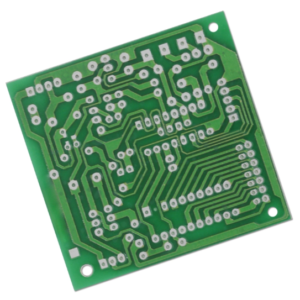
- Copper pad design: Each hole has a round pad for soldering. Pads can be independent or pre-connected in strips (strip breadboard type).
- Two popular types: blank grid protoboard (all pads isolated) / bus-strip protoboard (power rails pre-connected)
- Stack-up:
- 1-layer: copper only on top side, bottom pure FR4, cheaper for simple circuits.
- 2-layer: top + bottom copper, can run hidden jumpers on the bottom to avoid messy wiring on top.
This board is not pre-wired like plastic solderless breadboard; it is a solderable prototyping PCB.
IV. Core Manufacturing Advantages
- Stable FR4 material with good flatness, less warpage under repeated hand soldering.
- Consistent 2.54mm hole position accuracy, pins and sockets can be inserted smoothly without forcing.
- Smooth pads and reliable surface finish: OSP / HASL keep good solderability for manual soldering.
- Customizable options: blank grid, power rail strips, pre-marked +5V/GND bus, custom board size.
- Large panelized production, low MOQ and competitive price for university labs, hobby retailers.
- Clear non-fading white silkscreen grid, easy to read even after multiple soldering operations.
- 100% open/short electrical test before shipment.
V. Signal & Electrical Performance
- Insulation between isolated pads: High insulation resistance, low leakage current for low-voltage analog and digital prototype circuits.
- Bandwidth: Suitable for DC, low-frequency digital signals, analog sensor signals, up to several MHz. Not designed for high-speed RF / high-frequency signals.
- Current capacity:
- 1oz copper (35μm): ~2–3A per single track (depends on track width)
- 2oz copper (70μm): ~4–6A for power supply tracks
- EMC performance: No built-in ground plane by default. Users need to add ground wires manually for noise-sensitive circuits.
- Application limit: Mainly for low voltage DC prototype (5V, 12V, 24V). Not for high voltage or high-power continuous heavy load.