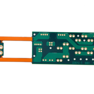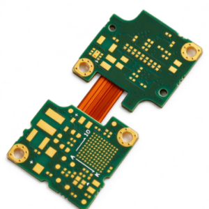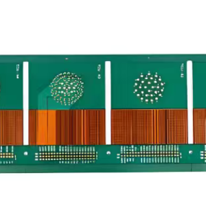
Our Multi-layer Flexible Rigid PCB integrates FR4 rigid sections and polyimide flexible layers, specially engineered for compact wearable electronics.Custom multi-layer rigid-flex PCB combines FR4 rigid sections and polyimide (PI) flexible layers, built for compact wearable electronics. It merges mechanical bending capability with stable electrical performance, eliminates extra connectors and cables to shrink product size, widely adopted in smart watches, health trackers, smart glasses and wearable medical sensors.
1. Specification & Parameters
- Material: Rigid part: FR4; Flexible part: Polyimide (PI), optional halogen-free PI
- Layer count: Custom 2–12 layers (mixed rigid + flex stackup)
- Finished thickness: Rigid zone 0.4–1.6mm; Flex core 0.05–0.2mm
- Copper foil: Rolled annealed copper 12μm / 18μm for flex area; 1oz / 0.5oz for rigid area
- Min trace / space: 0.075mm / 0.075mm, HDI option down to 0.05mm/0.05mm
- Min hole size: Mechanical hole 0.2mm; Laser microvia down to 0.1mm
- Surface finish: ENIG, ENEPIG, OSP, Immersion Silver
- Min dynamic bend radius: 3–6 × flex thickness; Dynamic bending life ≥50,000 cycles
- Operating temperature: -40℃ ~ +125℃
- Compliance: IPC-2223, IPC Class 2 (optional Class3 for medical wearables)
2. Manufacturing & Process Advantages
- Integrated lamination with no-flow PP, smoothly bonds FR4 and PI layers, reduces delamination risk at rigid-flex transition zone.
- Stress relief design with tear stops and rounded fillets at flex-rigid boundary to prevent copper cracking during repeated bending.
- Precision laser drilling for microvias, supports high-density routing in limited wearable internal space.
- Strict layer alignment control, layer-to-layer offset ≤ ±0.05mm.
- Full inspection: X-ray, AOI, impedance coupon test, bend fatigue test, thermal cycling test before shipment.
- Prototype & mass production available, DFM review before fabrication to avoid manufacturability issues for wearable compact layout.
- Optional stiffener reinforcement (PI/FR4) on rigid-flex transition for component soldering stability.
3. Impedance Characteristics
- Common target impedance: 50Ω single-ended, 90Ω /100Ω differential pairs for MIPI, USB, low-power high-speed wearable signals.
- Impedance tolerance: ±10% standard, ±5% for premium high-speed wearable designs.
- Special stack-up compensation: PI dielectric constant (Dk 3.2~3.5) differs from FR4, we recalculate trace width separately for rigid and flex regions.
- TDR impedance test coupon on panel to verify actual impedance value; Compensate trace width to offset slight impedance shift caused by repeated bending.
- Differential pair length skew control to maintain signal integrity across rigid-flex transition.
4. Signal & Electrical Performance
- Low insertion loss and low crosstalk, stable signal transmission during bending motion.
- Continuous ground plane design suppresses EMI/EMC interference, critical for biometric sensing (PPG, ECG) wearables.
- Insulation resistance ≥10¹² Ω, withstand voltage meets wearable low-voltage circuit requirements.
- Consistent current carrying capacity on both rigid and flex zones, suitable for battery charging & low-power sensor circuits.
- Minimal signal discontinuity at rigid-flex transition; avoids impedance jump brought by separate connectors.
- Low capacitance variation under bending, keeps sensor reading stable for health monitoring wearables.
5. Application Scenarios
Smart watches, fitness trackers, smart AR glasses, wearable ECG/PPG health sensors, hearing aids, wearable camera modules, portable wearable IoT devices.