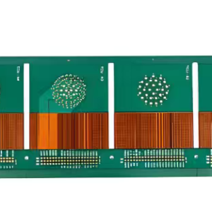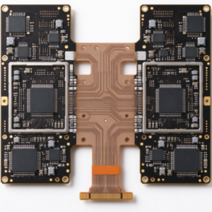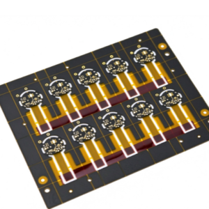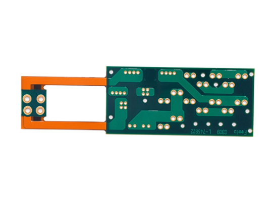
FR4 + Polyimide Rigid-Flex Board combines the rigid structural support of FR-4 printed circuit boards with the flexible bending capability of polyimide (PI) film. This hybrid construction allows the board to fold into compact 3D shapes while maintaining reliable SMT assembly on rigid sections, making it ideal for industrial electronic devices with space constraints.
I. Specifications
| Item | Specification |
|---|---|
| Board Type | FR4 + Polyimide Rigid-Flex PCB / Rigid-Flex Board |
| Rigid Material | FR-4 (TG130 / TG150 / TG170, optional) |
| Flexible Material | Polyimide (PI, 12.5μm / 25μm / 50μm core) |
| Copper Foil | Rolled Annealed Copper (RA Copper) 18μm / 35μm |
| Coverlay | PI coverlay with adhesive / Adhesiveless PI coverlay (optional) |
| Solder Mask (Rigid Area) | Green / Black / White / Blue solder mask; Liquid photoimageable solder mask |
| Coverlay Color (Flex Area) | Amber / Black PI coverlay |
| Min. Line Width / Line Space | 0.075mm / 0.075mm |
| Min. Hole Diameter | 0.15mm (laser microvia), 0.2mm mechanical drill |
| Board Thickness (Rigid Part) | 0.8mm, 1.0mm, 1.2mm, 1.6mm |
| Flexible Layer Thickness | 0.05mm ~ 0.2mm (PI base + copper + coverlay) |
| Layer Count | 2~12 layers rigid-flex, customizable |
| Impedance Control | ±10%, ±5% (controlled differential / single-ended impedance) |
| Surface Finish | ENIG (Gold 0.05~0.1μm), HASL, OSP, Immersion Silver |
| Operating Temperature Range | -40℃ ~ +125℃ |
| Bending Radius | ≥ 6×flex thickness (dynamic bending); ≥3×flex thickness (static fold) |
| Max Bending Cycles | ≥100,000 cycles (adhesiveless PI + RA copper, dynamic bending) |
| Tolerance | ±0.1mm outline tolerance |
| Certification | IPC-6013, RoHS, REACH |
II. Features
- Combine the rigidity of FR4 and flexibility of Polyimide: rigid zones for component soldering, flexible zones for folding, interconnection between separated industrial modules.
- Excellent high-temperature resistance of PI, stable performance under continuous industrial working temperature.
- Good vibration & shock resistance, reduce connector harness failure in vibrating industrial equipment.
- Compact 3D assembly, replace multiple wiring cables & connectors, save internal space of industrial electronics.
- Stable high-speed signal transmission, support differential signals for industrial bus, LVDS, RS485, Ethernet.
- Low creep, good dimensional stability, suitable for long-lifetime industrial applications.
- Adhesiveless PI option available for better bending life and lower signal loss at high frequency.
III. Design Principle
An integrated rigid-flex board—combining an FR4 rigid section with a polyimide (PI) flexible section—this is not merely a simple connection between an FR4 board and an FPC.
- Rigid zone (FR4): Designated for component mounting, BGA placement, and connector soldering. The FR4 material provides mechanical support, ensuring the board remains undeformed during SMT assembly and reflow soldering—ideal for high-density component placement.
- Flex zone (Polyimide): Designed for bending and dynamic interconnection. With high thermal resistance and excellent fatigue resistance, the PI material serves as a replacement for traditional wire harnesses, enabling flexible connectivity between two rigid board sections.
- Transition zone (Rigid-flex interface): This is the most critical design challenge. High-density routing and the placement of solder pads are strictly prohibited in this area. Copper traces must incorporate “teardrops,” and the copper foil grain should be oriented along the direction of the bend to prevent fractures during flexing.
- Stack-up planning: Signal layers and reference ground planes must be positioned in close proximity. Impedance control relies on the thickness of the dielectric layers; since the flex zone uses PI and the rigid zone uses FR4—materials with different dielectric constants—impedance must be simulated separately for each region.
Dielectric constant: FR4 ≈4.2, Polyimide ≈3.4
IV. Core Manufacturing Advantages
- Integrated lamination process:One-piece rigid-flex structure, no soldered joints between rigid board and FPC, avoid contact failure.
- Controlled transition area treatment:Stress relief design at rigid-flex boundary, reduce cracking risk after repeated bending.
- Laser ablation for flex window:Laser opening to expose flexible area, clean edge, no mechanical burr, protect PI dielectric.
- RA rolled copper for flexible circuit:Rolled annealed copper instead of ED copper, much better anti-fatigue bending performance.
- Selective coverlay & solder mask:Flex area only use PI coverlay (no FR4 solder mask on flex part, mask will cause brittle fracture).
- Vacuum lamination & low-stress pressing:Prevent delamination between FR4, adhesive and PI film, improve long-term reliability for industrial use.
- 100% electrical continuity test + bending sample validation for industrial orders.
V. Signal & Electrical Performance
- Insulation resistance: ≥10¹² Ω·cm, PI material maintains high insulation under humidity and temperature cycling.
- Dielectric loss: PI has lower Df than FR4, better for medium-high speed industrial differential signals.
- Impedance consistency warning: FR4 and PI have different Dk, same line width will get different impedance value in rigid / flex section, we do stack-up simulation separately.
- Signal integrity: Reduce parasitic inductance from cables & connectors; shorter interconnection path, less EMI noise in industrial EMC environment.
- Voltage rating: Depend on dielectric thickness; standard design supports 50V~500V industrial low-voltage circuits.
- ESD performance: Cooperate with ground plane design, convenient for EMC/ESD protection required industrial electronics.