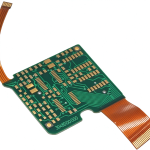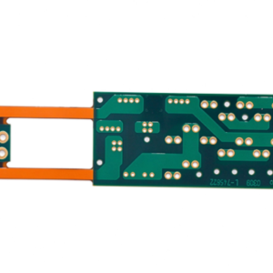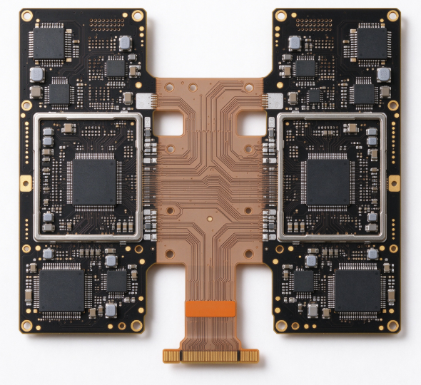
Rigid-Flex Boards combine rigid FR4 substrate and flexible polyimide film, supporting bending and folding to fit compact 3D assembly space. They are widely used for medical instruments, aerospace and wearable electronic products.
Specifications (Medical / Aerospace Grade)
| Project | Specification | Specification |
|---|---|---|
| Structure | Rigid Multilayer (4–16 Layers) + Flexible Core Combination | The flexible layer can be embedded or located on the surface |
| Flexible substrate | PI 12.5–25 μm, RA/ED copper | RA copper has a high flexural life |
| Line width/line spacing | 4/4 to 3/3 MIL (flexible zone) | Routing in the flexible zone should be generous to prevent breakage |
| Bending radius | Dynamic: ≥10× slice thickness; Static: ≥3× | Key reliability parameters |
| Temperature resistance | PI -65~150℃ | Medical disinfection, aviation environments |
| Certification | IPC-6013 (Flex), UL, Aerospace-grade (e.g., NASA / Military specifications) | Essential needs in healthcare and aviation |
| Certification | Resistant to humidity, salt spray, and vibration/shock | High requirements for reliability verification |
Performance characteristics
- High Reliability: One-piece molding eliminates connectors and solder joints, drastically reducing potential points of failure—a primary reason for its use in medical (implants/monitoring) and aerospace (vibration/shock) applications.
- Lightweight and miniaturized: Eliminates wire harnesses and connectors, reducing weight and size—ideal for aerospace and portable medical applications.
- 3D Assembly: The flexible section can be folded and bent to fit compact and irregularly shaped cases.
- Flex life: RA copper + PI structures can withstand tens of thousands to 100,000 dynamic bending cycles.
- Excellent signal integrity: The flexible zone allows for precise impedance control (microstrip/stripline), and high-speed signals can be routed on the inner layers.
- Strong environmental adaptability: resistant to temperature, humidity, and vibration/shock; meets rigorous certification standards.
Design Principle (Key to High Reliability in Medical/Aviation)
- Routing in the bend zone: Route traces perpendicular to the bend axis; no vias, pads, or coverlay openings are permitted—these are points prone to stress-induced breakage.
- Transition Zone Buffering: A flexible extension (transition section) and rounded corners are required at the interface between rigid and flexible zones to prevent tearing caused by stress concentration.
- Copper foil selection: Use RA (rolled-annealed) copper for dynamic bending applications; avoid abrupt changes in thickness.
- Stack-up design: Position the flexible layer symmetrically and centrally (at the neutral axis) as much as possible to minimize the stress difference between the inner and outer layers during bending.
- DFM / Interlayer Alignment: Positioning of flexible layers, resin flow, and interlayer alignment accuracy are critical to the rigid-flex lamination process; medical and aerospace applications demand rigorous traceability and testing.
- Reliability testing: thermal cycling, temperature-humidity, vibration, flexural endurance, insulation/dielectric withstanding voltage, ionic contamination, etc., conducted in accordance with IPC-6013 Class 3 / aerospace-grade standards.
Solder mask and surface characteristics
- A flexible PI coverlay (bendable) is used to protect the flexible zones, with cutouts exposing the pads; conventional solder mask is used for the rigid zones.
- Surface treatment for rigid zones commonly employs ENIG (offering oxidation resistance and good solderability), while aerospace and medical applications require lead-free or compliant materials.
- The edges of cutouts in the coverlay should be rounded to avoid stress concentration; brittle solder mask ink should not be used in the flexible zones.
Signal performance characteristics
- The flexible zone can be designed with microstrip or stripline structures for impedance control, supporting high-speed differential signals (such as LVDS, SERDES, and PCIe).
- Multilayer rigid-flex boards allow for the embedding of high-speed lines in inner layers, offering excellent shielding and controllable crosstalk.
- Note: Bending in the flexible zone will slightly alter impedance, so design margins should be allowed; high-frequency/high-speed traces should avoid areas subject to severe bending as much as possible.
Volectronics Tech Co., Ltd is your one-stop PCB prototype fabrication and assembly partner — a leading PCB manufacturing company. From single-layer to complex multilayer boards, we deliver high-quality PCBs backed by UL, ISO, RoHS, and IPC compliance.
Welcome to contact us for a quote!