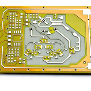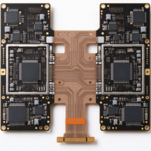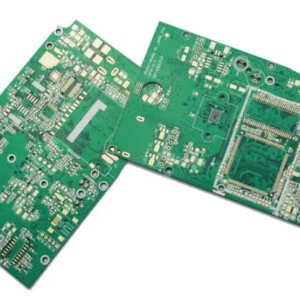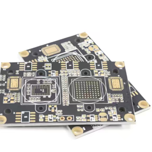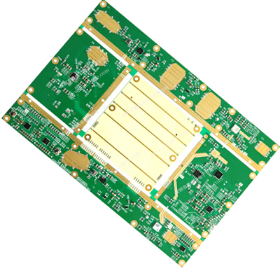
High-Frequency PCB is designed for RF and microwave signal transmission, featuring low dielectric loss and stable Dk value. It is widely used in radar, satellite communication, 5G base station, antenna and wireless radio frequency equipment.
I. Material Properties
| Parameter | Explanation | Typical value |
|---|---|---|
| Dielectric constant Dk | Determines impedance and signal delay; the lower the value, the easier it is to match | PTFE 2.2 / Hydrocarbon 3.48 / High Dk 6–10 |
| Dielectric Loss (Df) | This determines the insertion loss; the lower the value, the less the signal attenuation | High-end 0.0009–0.002, FR4 0.02 |
| Frequency stability | Dk/Df changes little with frequency | Key material indicators |
| Temperature coefficient | Low CTE, dimensional stability, and reliable welding | Low-expansion series |
| Copper foil roughness | Copper foil roughness | HVLP / Ultra-low roughness copper |
II. Manufacturing process parameters
- Impedance control: 50/75 Ω, tolerance ±5–10% (stricter for high frequencies); requires in-line impedance testing.
- Trace width / spacing: Determined by RF design (typically wider, but with strict impedance matching requirements).
- Layer Count / Mixed Stack-up: Common configurations involve mixed lamination—combining high-frequency materials (RF layers) with FR4 (inner layers/power & ground planes)—to balance performance and cost; all-high-frequency multilayer designs are also produced.
- Surface finish: ENIG (Electroless Nickel Immersion Gold) or gold plating, to prevent oxidation from affecting RF contact.
- Thickness: PTFE-based materials often require localized thin dielectric layers to achieve high isolation or specific impedance.
III. Performance characteristics
- Low insertion loss: Low Df + low-profile copper + uniform glass fiber → minimal signal attenuation over long-distance transmission; this is the most critical performance characteristic of high-frequency boards.
- Impedance Stability: Excellent Dk consistency → 50Ω matching, low return loss, minimal reflection, and efficient signal power transmission.
- Phase Consistency: Excellent control of the fiberglass weave effect ensures stable phase/delay across batches, making it suitable for phased array and beamforming applications.
- High-frequency reliability: resistant to temperature and humidity, and resistant to delamination; proper treatment of mixed-lamination interfaces ensures no delamination occurs.
- Shielding / Isolation: Multiple embedded ground/power planes suppress crosstalk and radiation.
IV. Application scenarios
| Field | Typical applications |
|---|---|
| Communication base station | 5G/4G Power Amplifiers, Antennas, RRUs, Combiners |
| Satellite/Radar | Satellite communication, phased-array radar, millimeter-wave radar |
| Automotive electronics | 77GHz automotive radar, V2X, automotive antennas |
| Defense / Aerospace | Radar, electronic warfare, and navigation |
| High-speed digital | High-speed backplanes, AI/server interconnects (low-loss FR4/M-series) |
| Medical/Testing | Medical equipment, RF test boards, instrumentation |
Founded in 2017, Volectronics Tech Co., Ltd is committed to providing one-stop services for samples and small-to-large volume orders.
We offer a diverse selection of PCB material, including FR4, Rogers, Metal based, TU, Isola, PI, and other high-frequency material, providing a wide range of options to meet your specific requirements.
We offer Aluminum PCBs, Flex PCBs and all types of circuit boards for sale, every order, regardless of size, receives the utmost attention to detail throughout the entire process to ensure all customer expectations are met.