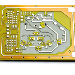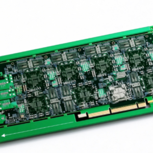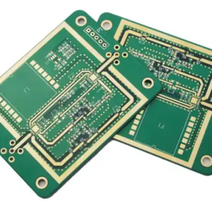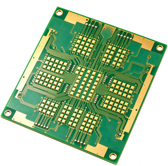
Our OEM custom low-loss High Frequency PCB adopts Rogers or PTFE substrate, featuring ultra-low dielectric loss and stable Dk performance for RF and millimeter-wave applications.
✅ Core Selling Points
- Low Dk / Low Df dielectric material (Rogers / PTFE), minimal signal attenuation at high frequency, stable dielectric constant over wide frequency band
- Custom OEM service, support prototype & mass production, impedance controlled ±5% / ±10% optional
- Excellent high-frequency signal integrity, suitable for millimeter wave, RF communication, radar and antenna systems
- High temperature resistance, low thermal expansion, stable electrical performance under changing temperature
- Strict IPC class 2 / Class3 available, RoHS & REACH compliant
- Precision microvia, fine line & space, copper thickness customization; bonding film / prepreg hybrid stackup available
- Fast sampling turnaround, DFM review before production to avoid design risk
✅Specification Table
| Item | Specification |
|---|---|
| Base Material | Rogers (RO4003C, RO4350B, RO5880 etc.), Pure PTFE, PTFE + Glass Fiber, Hybrid RF Stackup |
| Dielectric Constant (Dk) | 2.2 ~ 10.2 (depends on material) |
| Dissipation Factor (Df) | Ultra low loss: 0.0009 ~ 0.003 @10GHz |
| Layer Count | 1~16 layers, hybrid FR4 + Rogers mixed stackup supported |
| Copper Foil Type | ED copper / Reverse Treat Foil (RTF) / Low profile copper foil |
| Impedance Control | Single-ended / Differential impedance, tolerance ±5%, ±8%, ±10% |
| Min Line Width / Space | 3mil /3mil |
| Min Hole Size | 0.15mm mechanical hole, 0.075mm laser microvia |
| Board Thickness | 0.2mm ~ 3.2mm, custom thickness available |
| Surface Finish | Immersion Gold, Hard Gold Plating, HASL, OSP, Immersion Silver, Tin |
| Solder Mask | Liquid photoimageable solder mask (green/black/blue/red), also available without solder mask for antenna |
| Frequency Range | Up to mmWave band (24GHz, 28GHz, 39GHz, 77GHz etc.) |
| Standard | IPC-6012, RoHS, REACH |
✅Design Principle
High frequency RF PCB relies on controlled dielectric constant and low-loss substrate. At microwave & millimeter wave frequency, ordinary FR4 has high Df, which causes serious signal loss, phase shift and signal distortion. PTFE / Rogers ceramic filled PTFE materials feature stable Dk and ultra-low dissipation factor. Designers calculate trace width, substrate thickness and copper thickness to hit target impedance (50Ω, 100Ω differential mostly). We adopt stripline / microstrip / grounded coplanar waveguide (GCPW) structure for RF signal routing; separate RF signal path from power & ground to reduce crosstalk and parasitic capacitance. Hybrid stackup design combines low-cost FR4 for digital layers and Rogers/PTFE for RF layers to balance performance and cost.
✅ Performance Characteristics
- Stable dielectric property: Dk changes little with frequency, temperature and humidity, consistent RF phase response
- Ultra-low signal loss: Much lower insertion loss than standard FR4, critical for long-range RF transmission
- Low thermal expansion: Low CTE, less layer delamination, good dimensional stability during SMT reflow
- Low moisture absorption: Almost not absorb water, electrical performance won’t drift in humid environment
- High breakdown voltage: Good insulation property, suitable for high-power RF circuit
- Good anti-interference performance when paired with complete ground plane design
✅ Manufacturing & Process Advantages
- Professional RF stack-up engineering team, DFM pre-check for high-frequency impedance design
- Special lamination process for PTFE / Rogers material, avoid substrate deformation, delamination and void
- Laser direct drilling for microvias, high positional accuracy for fine pitch RF circuits
- Special etching process for low-profile copper, reduce conductor loss at high frequency
- Strict impedance testing: Time Domain Reflectometry (TDR) test report available on request
- Special surface treatment for RF board: avoid rough copper surface that increases high-frequency loss
- Support mixed stackup Rogers + FR4, help customer cut material cost while keeping RF performance
- Antenna version option: no solder mask on radiation area to prevent loss from solder mask
✅ Typical Application Scenarios
- Millimeter wave radar, automotive 77GHz radar
- 5G / 6G RF antenna, phased array antenna
- Satellite communication, microwave radio, point-to-point RF transceiver
- RF power amplifier, filter, coupler, mixer
- Test & measurement instrument, RF sensor
- Wireless communication module, IoT high-frequency radio unit