
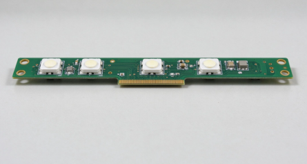
LED PCB design is different from designing ordinary circuits. LEDs are current-driven, heat-sensitive, and often exposed to harsh conditions. Get the PCB design wrong and your LEDs will flicker, overheat, or die early — even with perfectly good components.LEDs are current-driven, heat-sensitive, and often exposed to harsh conditions. Get the PCB design wrong and your LEDs will flicker, overheat, or die early — even with perfectly good components.
This guide covers the key design factors that determine how well an LED board performs: thermal management, copper layout, LED circuit topology, and pad design.
Why LED PCB Design Is Different
LEDs don’t behave like most components. Two things make them special:
- They are current-driven— brightness depends on controlled current, not just voltage.
- They generate heat at the junction— and that heat must be moved away or the LED degrades.
A well-designed LED PCB handles both: it delivers stable current and pulls heat off the LED. A poorly designed one fails at one or both.
Thermal Management Is Everything
Heat is the number-one killer of LEDs. When the junction temperature rises, an LED loses brightness, shifts color, and wears out faster. The PCB is the primary path for heat to leave the LED.
Key thermal decisions in LED PCB design:
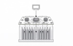
- Board material— a metal-core board (MCPCB) conducts heat far better than standard FR-4.
- Copper area under the LED— a larger copper pad spreads heat away from the junction.
- Thermal vias— vias under the LED pad help move heat to other layers or the metal core.
- Board layout— group LEDs with spacing that avoids concentrating heat in one spot.
For high-power LEDs, an MCPCB is usually the right call. For low-power indicator LEDs, FR-4 with generous copper may be enough.
LED Circuit Topology: Series vs. Parallel
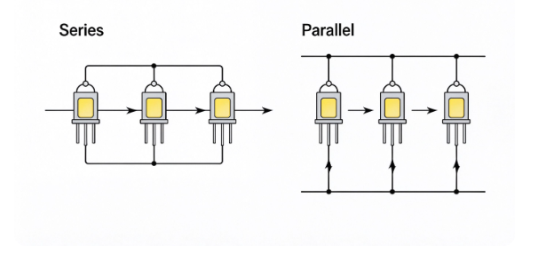
How you connect the LEDs changes the PCB layout and reliability.
| Topology | Current | Brightness | Reliability |
| Series | Same current through all LEDs | Uniform | Better — one failure opens the string, not the whole board |
| Parallel | Split per branch | Can vary | Weaker — current imbalance if LEDs differ |
Most designs use series strings with a constant-current driver, because series gives uniform brightness and predictable current. Parallel branches need careful current balancing.
Copper Traces and Current Capacity
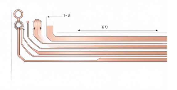
LEDs can draw significant current, especially in high-power lighting. The copper traces must carry that current without overheating.
Design rules for LED traces:
- Widen traces for high current— narrow traces overheat and drop voltage.
- Match trace width to the LED current and trace length.
- Use solid copper pours where possible to aid both conduction and heat spreading.
- Watch the return path—— the ground return carries the same current.
Pad Design for LED Mounting
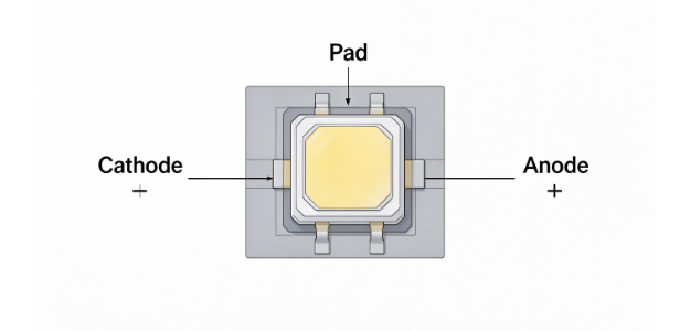
The pad under each LED affects both solder quality and heat transfer.
- Correct pad size— match the LED package so it self-aligns during reflow.
- Thermal pad— a larger thermal pad under high-power LEDs spreads heat.
- Solder mask openings— keep the mask off the pad so solder wets properly.
- Cathode/anode marking— clear polarity marks prevent wrong orientation.
Light Emission and Placement
Beyond electronics, the PCB layout affects how light comes out of the board:
- Keep LEDs aligned for even light distribution.
- Avoid traces or mask that block the light path.
- Consider reflector and optic mounting if the design uses lenses.
Protection and Reliability
LED boards often run outdoors or in demanding environments. Design for:
- Reverse-polarity and surge protection at the input.
- ESD protection on exposed LED inputs.
- Conformal coating for humid or dirty environments.
- Correct surface finish for solderability and corrosion resistance.
Prototype Before You Commit
LED PCB design has many interacting factors — thermal, electrical, and optical. A quick prototype, tested at real operating current and temperature, reveals problems long before full production.
At Volectronics Tech Co., Ltd, we design and build LED PCBs — from metal-core boards for high power to FR-4 boards for simple indicators — with the thermal and electrical layout reviewed before production so your LEDs stay bright and last.