
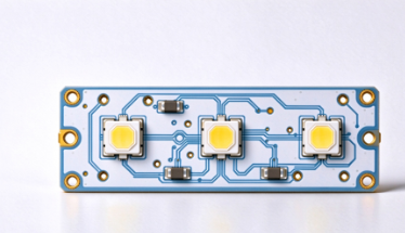
SMT PCB Assembly for MCPCB LED Modules has unique thermal challenges. High-power LEDs fail mostly from heat. That’s why engineers choose MCPCB (metal core PCB, usually aluminum core) instead of regular FR4 boards. But MCPCB LED SMT assembly is not the same as standard PCB assembly.
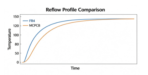
The same metal core that dissipates heat during operation also acts like a giant heat sink during reflow soldering. It pulls heat away from solder joints easily, creating cold joints, uneven temperature distribution, delamination or voids under LED thermal pads if the process is not tuned properly.
In this guide, we break down MCPCB LED SMT assembly, its benefits, critical process adjustments, common mistakes and design rules you can share with your EMS partner.
I. What is MCPCB LED SMT Assembly?
MCPCB LED assembly means mounting SMD LEDs, driver ICs, resistors, capacitors and connectors onto aluminum-core PCBs via automated SMT lines.
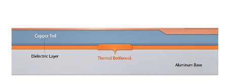
A typical aluminum MCPCB stack-up:
- Copper trace layer (1oz ~ 4oz copper, high thermal spreading)
- Thermally conductive dielectric layer (the thermal bottleneck of the whole board)
- Thick aluminum base core for heat spreading
Common LED packages: 2835, 3030, 5050, 5630, high-power COB LEDs, UV LED chips. Most MCPCB LED designs use single-sided SMT placement; double-sided assembly is rare and complicated for metal core substrates.If you are unsure which soldering method fits your project, check our comparison of SMT assembly vs DIP assembly.
II. Why Pair SMT Assembly with MCPCB for LED Products?
- Superior thermal path: Heat flows directly from LED pad through dielectric to aluminum core, reducing junction temperature, lumen depreciation and color shift
- High repeatability: Automated pick-and-place guarantees consistent LED polarity, placement offset and solder volume for mass lighting production
- Compact module design: Ideal for spotlights, UV curing lamps, automotive LED, panel lights, high-bay lights and compact power lighting
- Longer service life: Well-controlled MCPCB SMT assembly can extend LED lifespan and reduce field returns
III. The Biggest Difference: Reflow Profile Tuning for MCPCB
This is the #1 difference from FR4 SMT. Aluminum core absorbs heat quickly, so a standard FR4 reflow recipe will fail.
Key reflow rules for MCPCB LED assembly (SAC305 lead-free solder):
- Extended soak zone (150–180°C, 90–120s) to equalize temperature across the aluminum mass
- Slow, controlled ramp-up; avoid sharp temperature spikes
- Peak temperature: 240–250°C
- Time above liquidus (TAL): 60–90 seconds
- Always run thermal profiling with thermocouples attached to LED thermal pad area, not just board edge
If the soak time is too short: hot and cold spots appear. Cold solder joints, poor wetting and high void rate under LED thermal pads follow. If peak temp is too high: dielectric layer risks delamination, mask discoloration and long-term insulation failure.
IV. Critical Process Checkpoints in MCPCB LED SMT Line
1. Solder Paste Printing
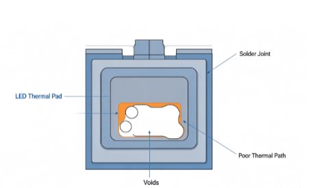
The large thermal pad under high-power LEDs is where most voids happen.
- Use stencil design optimized for thermal pads: split apertures, not one big solid opening
- Stencil thickness control: too thick = excess solder and voids; too thin = insufficient solder
- Clean stencil frequently to avoid paste build-up
2. Pick & Place
LEDs are polarity-sensitive.
- Vision alignment must confirm LED marking direction
- Vacuum nozzle selection matched to LED package size; avoid chipping LED lenses or damaging phosphor layers
- Feeder management for high-volume LED runs to reduce missing components
3. Void Control (Most Important for High-Power LEDs)
Voids break the thermal path between LED and MCPCB. Even a small void percentage pushes junction temperature higher.
Best practices: optimized stencil design, proper reflow ramp, clean pad surface, low-void solder paste, nitrogen reflow option for premium UV / automotive LED modules.
4. Inspection & Testing
AOI catches missing LEDs, polarity reversal, tombstoning and bridging. For high-reliability projects: add X-ray inspection on LED thermal pads to measure void ratio. After SMT: electrical test, color bin verification, thermal cycle screening for critical applications.
V. Common Defects in MCPCB LED SMT & Root Causes
- Cold solder joints→ aluminum core drains heat too fast; insufficient soak time
- High voiding under LED thermal pad→ bad stencil aperture, paste drying, improper reflow ramp
- Delamination / dielectric split→ over-temperature, fast thermal shock, poor MCPCB material quality
- LED color inconsistency→ bin mixing, placement offset affecting optical angle
- Tombstone on small passives→ uneven paste volume and temperature gradient across the board
VI. Design Guidelines Before SMT Assembly
These layout rules help your assembler get higher yield:
- Keep high-power LED thermal pads as solid copper, connected directly to MCPCB thermal path
- Use high-thermal-conductivity dielectric when heat flux is high
- Select reflective white solder mask (high reflectivity, low yellowing) for optical performance
- Avoid placing heat-sensitive ICs right next to high-power COB LEDs
- Keep LED pad spacing consistent; crowding creates thermal stacking
- Prefer single-sided layout; avoid double-sided SMT on aluminum MCPCB
VII. Applications of MCPCB LED SMT Assemblies
- General commercial LED lighting: panel lights, strip lights, downlights
- High-power UV LED modules for curing, disinfection
- Automotive lighting, AEC-Q reliable LED assemblies
- Industrial high-bay, flood lights
- Medical optical and analytical LED modules
VIII. When to choose MCPCB SMT vs standard FR4 LED PCBA?
✅ Pick MCPCB SMT: high watt density, compact enclosure, UV LED, COB LED, long lifetime requirement
✅ Pick FR4 SMT: low-power indicator LEDs, low heat, cost-sensitive simple boards
IX. Final Takeaway
MCPCB gives LEDs the thermal performance they need, but only if your SMT assembly partner treats it as a thermal system, not a regular PCB. The reflow profile, stencil design, void control and inspection workflow are the four pillars of reliable MCPCB LED PCBA.
Bad SMT on MCPCB wastes all the benefits of the aluminum core: hot LEDs, early lumen drop and unexpected failures. With the right process recipe, MCPCB SMT LED modules deliver stable brightness, consistent color and long service life for lighting OEMs.
X. Our Company
At Volectronics, we specialize in MCPCB fabrication and SMT assembly tailored for high-power LED applications. Our engineering team performs dedicated thermal profiling for every MCPCB batch, with controlled low-void soldering, AOI and optional X-ray inspection to secure long-term LED performance.
Looking for reliable MCPCB LED SMT PCB assembly service for your lighting project? Share your LED spec, power density, board file and reliability requirements. We provide turnkey MCPCB fabrication + SMT assembly with thermal profiling, low-void process and AOI / X-ray inspection.